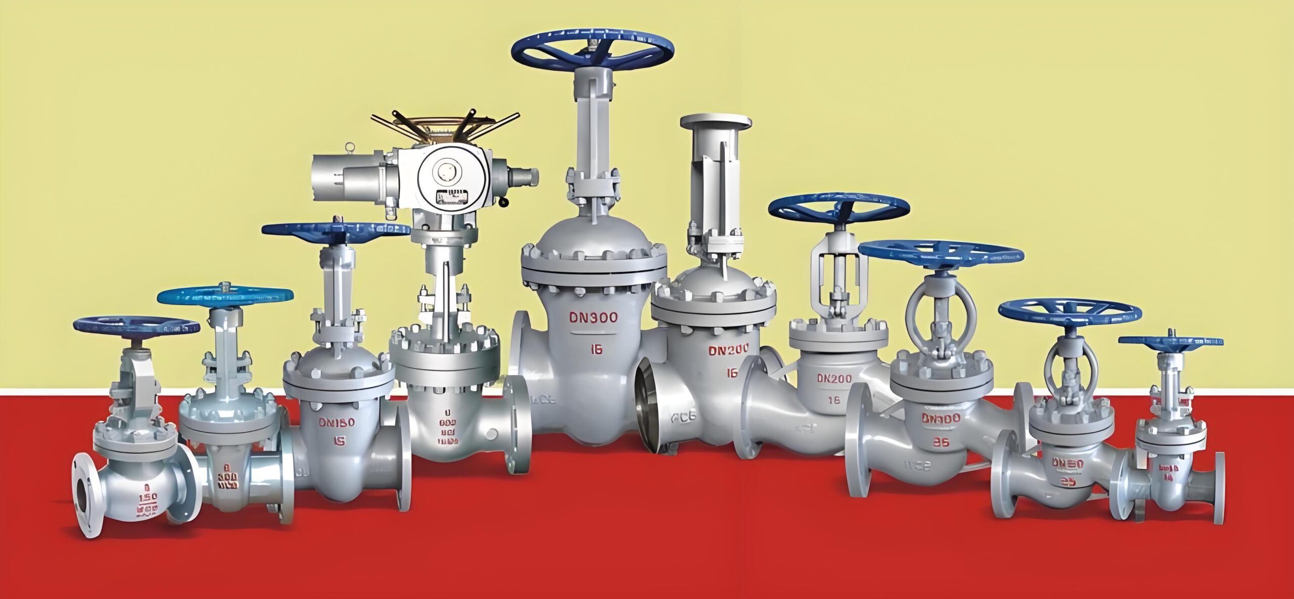
Valves, as the core control components of a fluid transfer system, their stable operation is critical to the safety and reliability of the entire system. To help you better understand and maintain these critical devices, a detailed guide to routine valve maintenance is provided below.
I. Appearance Maintenance
Clean the valve
Periodically remove dust, oil and rust spots from the valve surface. Use a soft and clean cloth or brush for cleaning, for difficult to remove stains, you can use appropriate cleaning agents, but need to ensure that the cleaning agent will not corrode the valve material. For example, a mild alkaline cleaner is recommended for stainless steel valves; for valves coated with paint, a cleaner that will not damage the paint should be used.
Also, make sure that the nameplate of the valve is clearly visible. The nameplate contains important information such as the valve’s model number, specification, pressure rating and date of manufacture, which is vital for operations such as maintenance, repair and replacement of the valve.
Checking Valve Integrity
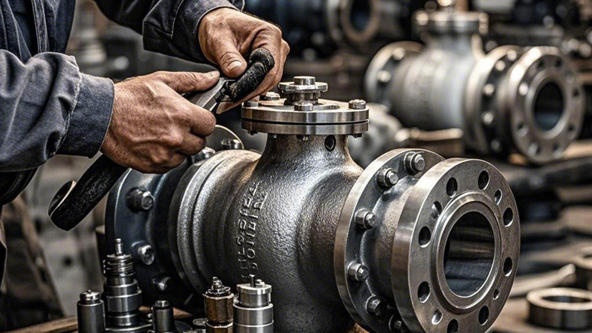
Carefully inspect the valve’s components such as the body, bonnet and flanges to ensure there are no signs of cracks, distortion or damage. Cracks can lead to media leakage, while deformation can affect the proper operation and sealing performance of the valve. For cast iron valves, special attention needs to be paid to check for leaks caused by casting defects such as sand holes.
Check the connection parts of the valve, such as flange connection bolts for looseness, detachment or corrosion. Loose bolts may affect the sealing performance of the flange and should be tightened in time; corroded bolts may need to be replaced to ensure the reliability of the connection. At the same time, check whether the gasket of the connection part is intact, if it is damaged or aging, it should be replaced in time.
Observe whether the operating parts such as handwheel, handle or electric actuator of the valve are intact. These parts are the key to controlling the valve’s switching, and damage may cause the valve to fail to operate properly. For example, damage to the handwheel may prevent the operator from accurately controlling the opening of the valve.
Second, the valve sealing test
External leakage detection
Check the stem sealing part of the valve to see if there is media seepage. You can apply a small amount of leak detection fluid (such as soapy water) around the valve stem to see if there are bubbles. If there are bubbles, the stem seal is leaking and the packing or seals need to be further inspected for damage or deterioration and may need to be replaced to solve the leakage problem.
At the same time, check the flange connections of the valve for leakage. Again, a leak detection solution can be used and the flange edges can be observed for bubbles coming out of the flange. For flanges with trace leaks, the bolts may need to be retightened or gaskets replaced to fix the leak. For severe leaks, the upstream and downstream valves will need to be closed and the pipeline emptied before repairs can be made.
Internal Leak Detection
Depending on the type of valve and the working medium, different methods are used to check for internal leakage. For globe valves and gate valves, internal leakage can be determined by closing the valve and then observing whether there is medium flow downstream of the valve. For example, in water systems, you can observe whether there is water seeping out of the downstream piping or whether the pressure drops; in gas systems, you can use a gas detection instrument to detect whether there is gas leakage downstream.
For ball and butterfly valves, internal leakage can be initially determined by checking the accuracy of the position indicator after the valve is closed. If the position indicator shows that the valve is completely closed, but there is still media leakage, there may be a problem with the sealing between the ball or butterfly plate and the valve seat. Need to further check the sealing surface of the valve seat whether there is wear and tear, scratches or impurities attached, if necessary, grinding or replacement of the valve seat.
Third, the valve operation performance test
Manual valve operation test
Regularly operate the manual valve to check whether the opening and closing of the valve is smooth. When opening and closing the valve, pay attention to feel whether the operating force is uniform, there is no stagnation or abnormal resistance. If operation is difficult, it may be caused by excessive friction between the valve stem and packing, foreign objects stuck in the valve body, or damaged valve parts.
Check whether the valve opening indication is accurate. For valves with opening indicators, such as regulating valves, observe whether the reading of the opening indicator matches the actual opening when operating the valve. Inaccurate opening indication may affect the flow control of the system and require calibration or repair of the indicator.
For frequently operated manual valves, watch for wear on the handwheel or handle. Excessively worn operating parts may affect the operator’s feel and even lead to uncontrolled operation. Hand wheels or handles that are badly worn should be replaced in a timely manner to ensure the safety and accuracy of valve operation.
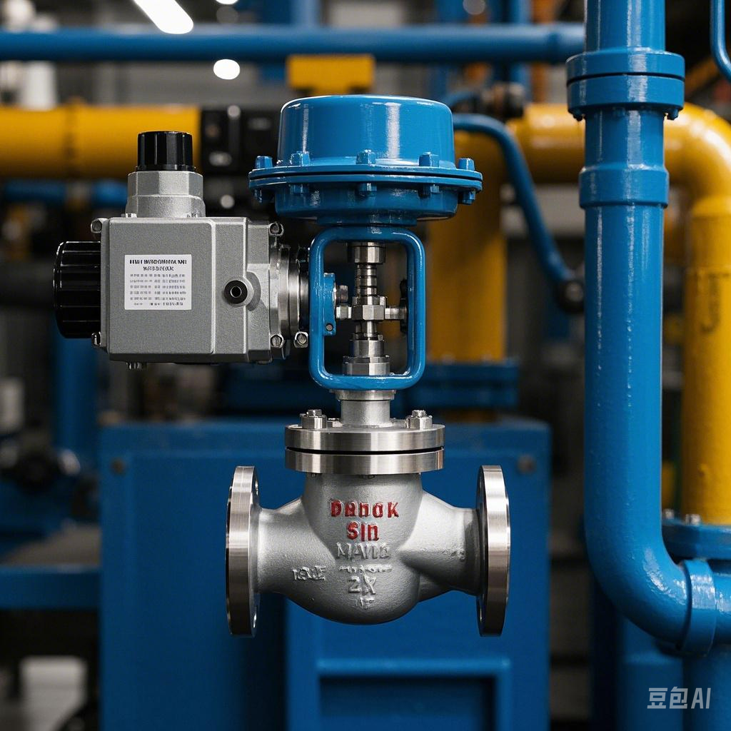
Motorized valve operation test
Check whether the power connection of the electric valve is normal and whether the wires are broken, aged or loose. Ensure that the control signal transmission of the electric actuator is normal, and you can operate the control system to check whether the valve can accurately open, close or adjust the opening degree according to the instruction.
Observe the action of the electric valve during operation, such as whether the opening and closing speed of the valve meets the requirements, and whether there is abnormal vibration or noise. Abnormal vibration or noise may be caused by damage to the internal parts of the electric actuator, failure of the valve mechanical structure or improper installation. Further inspection and maintenance of the electric valve is required, including checking the working condition of the motor, reducer, coupling and other components.
Regularly check and adjust the travel limit switch of the electric valve. The travel limit switch is an important device for controlling the opening and closing position of the valve. If the limit switch fails, it may cause the valve to open or close excessively, damaging the valve or the electric actuator. Check whether the limit switch can accurately cut off the power supply of the motor by simulating the full opening and closing action of the valve to ensure the safe operation of the valve.
Fourth, lubrication and maintenance
Lubrication point check
Determine the lubrication points of the valve, these parts usually include the valve stem, bearings, gears and so on. For different types of valves, the location and number of lubrication points may vary. For example, the main lubrication points for gate valves are the contact areas between the valve stem and the gate and guide; ball valves require lubrication of the contact areas between the ball and the valve seat as well as the valve stem.
Check that the lubrication points are adequately lubricated. If the lubricant is insufficient, it may lead to increased friction between the parts, affecting the operating performance and service life of the valve. For some valves with grease injection ports, you can determine whether the lubricant at the lubrication point is sufficient by observing the grease injection port or checking the level of grease.
Select the appropriate lubricant
According to the valve’s working environment and component materials to choose the right lubricant. In normal temperature and normal pressure environment, lithium grease is a commonly used lubricant, which has good lubrication performance and anti-wear performance. For valves in high-temperature environments, high-temperature-resistant polyurethane grease or perfluoropolyether grease can be selected; in low-temperature environments, ester lubricants with good low-temperature fluidity are required.
For chemical corrosive working environment, such as valves in the chemical industry, it is necessary to choose lubricants with corrosion resistance. For example, fluorine grease can resist the corrosion of strong acids, alkalis and other chemicals, providing effective lubrication and protection for the valve. At the same time, it is also necessary to consider the compatibility of the lubricant with the valve seals and other component materials to avoid damage to the components due to the chemical properties of the lubricant.
Lubrication operation
For valves that require lubrication, lubricate in accordance with the correct method and cycle. For manual valves, lubricant can be injected into the lubrication point using a grease gun or oil can. When injecting lubricant, be careful to avoid over-injection, so as not to overflow the lubricant to contaminate the surrounding environment or affect the normal operation of the valve. For electric valves, some electric actuator internal self-lubrication system, you need to regularly check and replenish the lubricant; for no self-lubrication system of electric valves, to its external lubrication point for artificial lubrication.
After the lubrication is completed, operate the valve a few times, so that the lubricant can be evenly distributed on the surface of the components to give full play to the lubricating effect. At the same time, to clean up the lubricant overflow in the lubrication process, to maintain a clean environment around the valve.
V. Valve attachment inspection
Filter maintenance
If there is a filter installed upstream of the valve, it is necessary to regularly check whether the filter is clogged. Filter clogging will lead to reduced fluid flow, increased pressure loss, affecting the normal operation of the valve. You can determine whether the filter is clogged by observing the pressure difference between the two ends of the filter, when the pressure difference exceeds a certain limit, the filter needs to be cleaned or replaced filter element. When cleaning the filter, it is necessary to follow the correct operating procedures to avoid damage to the filter screen or other parts of the filter. For some precision filters, it may be necessary to use special cleaning equipment and cleaning agents. After cleaning, make sure the filter is installed correctly and sealed well.
Pressure gauge and safety valve check
Check that the pressure gauge near the valve is working properly. Observe that the gauge’s needle accurately indicates pressure and that the dial is clearly readable. If the gauge’s needle jumps, does not return to zero, or indicates inaccurately, the gauge’s internal components may be damaged or the pressure sensor may be malfunctioning, requiring the gauge to be calibrated or replaced.
For systems with safety valves installed, periodically check that the safety valves are in proper condition. Check that the opening pressure of the safety valve meets the requirements and that it opens accurately at the set pressure, releasing excess pressure. The performance of the safety valve can be checked by manual testing or specialized testing equipment. It is also necessary to check the sealing performance of the safety valve to avoid leakage under normal operating pressure.
Routine maintenance of valves is crucial. Through regular inspection and maintenance, possible problems with the valves can be found and solved in time, extending the service life of the valves and ensuring the safe and stable operation of the fluid transfer system. We hope this guide can help you better understand and maintain your valve equipment.
Valves: The Guardians of Fluid Systems and Their Routine Maintenance Guide